|
|
|
|
|
TM221CE24R
Modicon M221 gépvezérlő PLC, 24 I/O, relé kimenet, RS232/RS485, Ethernet Modbus TCP/IP 100...230 VAC


|
|
|
|
Digital Inputs Wiring Diagram (Positive Logic)

Wiring Diagram (Negative Logic)

Connection of the Fast Inputs

Relay Outputs Negative Logic (Sink)

(1) The COM0, COM1 and COM2 terminals are not connected internally. (2) To improve the life time of the contacts, and to protect from potential inductive load damage, you must connect a free wheeling diode in parallel to each inductive DC load or an RC snubber in parallel of each inductive AC load B Sink wiring (negative logic) Positive Logic (Source)

(1) The COM0, COM1 and COM2 terminals are not connected internally. (2) To improve the life time of the contacts, and to protect from potential inductive load damage, you must connect a free wheeling diode in parallel to each inductive DC load or an RC snubber in parallel of each inductive AC load A Source wiring (positive logic)
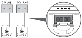
Analog Inputs


The (-) poles are connected internally. Pin | Wire Color |
|---|
0 V | Black | AN1 | Red | 0 V | Black | AN0 | Red |
Ethernet Connection

Pin N° | Signal |
|---|
1 | TD+ | 2 | TD- | 3 | RD+ | 4 | - | 5 | - | 6 | RD- | 7 | - | 8 | - |

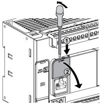
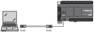
USB Mini-B Connection

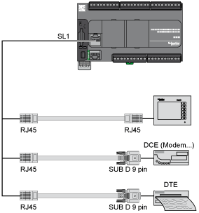
SL1 Connection

SL1 N ° | RS 232 | RS 485 |
|---|
1 | RxD | N.C. | 2 | TxD | N.C. | 3 | RTS | N.C. | 4 | N.C. | D1 | 5 | N.C. | D0 | 6 | CTS | N.C. | 7 | N.C*. | 5 Vdc | 8 | Common | Common |
N.C.: not connected * : 5 Vdc delivered by the controller. Do not connect.

|
|