|
Three-Phase Power Supply with Upstream Breaking via Line Contactor
Connection diagrams conforming to standards EN 954-1 category 1 and IEC/EN 61508 capacity SIL1, stopping category 0 in accordance with standard IEC/EN 60204-1
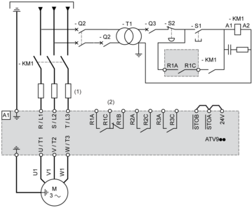
(1) Line choke if used (2) Use relay R1 set to operating state Fault to switch Off the product once an error is detected. A1 : Drive KM1 : Line Contactor Q2, Q3 : Circuit breakers S1, S2 : Pushbuttons T1 : Transformer for control part
Three-Phase Power Supply with Downstream Breaking via Contactor
Connection diagrams conforming to standards EN 954-1 category 1 and IEC/EN 61508 capacity SIL1, stopping category 0 in accordance with standard IEC/EN 60204-1
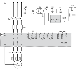
(1) Line choke if used (2) Use relay R1 set to operating state Fault to switch Off the product once an error is detected. A1 : Drive KM1 : Contactor
Control Block Wiring Diagram
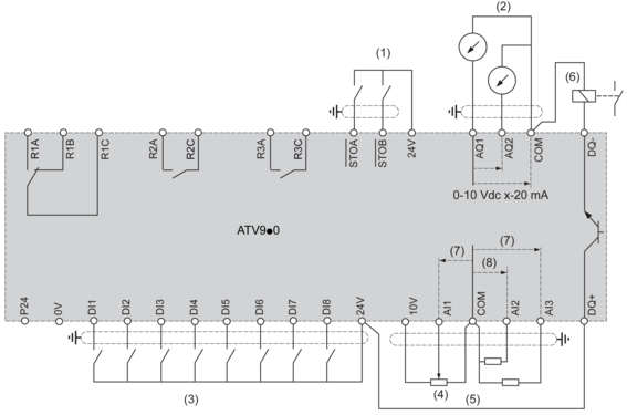
(1) Safe Torque Off (2) Analog Output (3) Digital Input (4) Reference potentiometer (5) Analog Input (6) Digital Output (7) 0-10 Vdc, x-20 mA (8) 0-10 Vdc, -10 Vdc...+10 Vdc R1A, R1B, R1C : Fault relay R2A, R2C : Sequence relay R3A, R3C : Sequence relay Sensor Connection
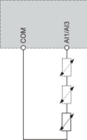
It is possible to connect either 1 or 3 sensors on terminals AI1 or AI3
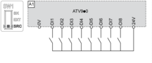
Sink / Source Switch Configuration
The switch is used to adapt the operation of the logic inputs to the technology of the programmable controller outputs. Switch Set to SRC (Source) Position Using the Output Power Supply for the Digital Inputs
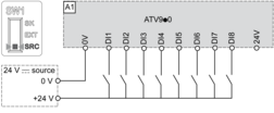
Switch Set to SRC (Source) Position and Use of an External Power Supply for the DIs
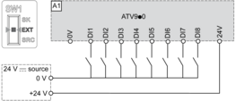
Switch Set to SK (Sink) Position Using the Output Power Supply for the Digital Inputs

Switch Set to EXT Position Using an External Power Supply for the DIs
|


